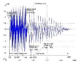
 DTMF signaling is a mechanism used in the PCM- TDM telephone network to represent digits with tone frequencies in order to transmit them over an analog telephone line. DTMF signaling is primarily used to encode the dialed number generated by a subscriber terminal that is to be processed by the subscriber’s access device. In addition, DTMF is popular in interactive applications, such as telephone banking or voice-mail systems, in which the user can select options from a menu by sending DTMF signals from the telephone.
The SGD generates DTMF mathematically using two digital oscillators. One of the most frequently used detection algorithms, and the basis of the SGD’s detection, is the Goertzel algorithm, which efficiently extracts the spectral information from the incoming signal.
Signaling Systems R1 and R2 are designed for information exchange over toll facilities. Signaling System R1 is used in North America while R2 is used in Europe. Both systems use MF tones for signaling.
Design Overview
The SGD can be thought of as a media-stream transform (MST). For receive, it accepts a PCM sample stream from the telephone network and transforms it to a data and event stream for an application program. For transmit, it accepts commands from the application program and generates a PCM stream.
For example, in DTMF/R1/R2 tone generation, the input stream is transformed (encoded) from a sequence of digits to combinations of specified frequencies. In DTMF/R1/R2 tone detection, the input stream is transformed (decoded) from a harmonic signal of specified frequencies to a sequence of digits. The signal (DTMF, MF/R1/R2, and a generic tone) generator is implemented in one MST, the DTMF and a precise tone detector in another MST, and the MF (R1&R2) tones detector are in a third MST. The figure below shows the above partitioning of the signal generator/detector MSTs.
DTMF/MF and Precise Tone Generation
The TONE MST accepts the following commands.
Input Commands
| Command Name |
Description |
| Gen_dtmf |
Starts DTMF generation. |
| Gen _R1 |
Starts MF/R1 generation. |
| Gen _R2F |
Starts MF/R2F generation. |
| Gen _R2B |
Starts MF/R2B generation. |
| Gen _tone |
Starts generic tone generation. |
| Stop |
Stops the TONE MST |
Parameters
The tables below show the TONE MST user-defined parameters for DTMF, MF, and a generic tone generation.
DTMF and MF Parameters
| Parm Name |
Type |
Default |
Units |
Description |
| Level 1 |
INT |
-6 |
dBm |
The level of the low frequency component of the DTMF pair. Valid range – 43 to –3. |
| Level 2 |
INT |
-4 |
dBm |
The level of the high frequency component of the DTMF pair. Valid range – 43 to –3. |
| LongPause |
INT |
5000 |
Msec |
The delay associated with the ‘.’ (period) character. Valid range 0-65535. |
| Off Time |
INT |
55 |
Msec |
The duration of the silence time between each DTMF digit. Valid range is 0–65535. |
| On Time |
INT |
45 |
Msec |
The duration of each DTMF digit. Valid range is 0–65535. |
| ShortPause |
INT |
2000 |
Msec |
The delay associated with the ‘,’ (comma) character. Valid range 0-65535. |
Generic Tone Parameters
| Parameter Name |
Type |
Default |
Units |
Description |
| Level 1 |
INT |
-20 |
dBm |
The level of the first (or only) frequency component. Valid range – 43 to –3. |
| Level 2 |
INT |
-4 |
dBm |
The level of the second frequency component (if any). Valid range – 43 to –3. |
| OffTime |
INT |
0 |
Msec |
The duration of silence between tones on time. Specify 0 for no off-time. Valid range 0-65535. |
| OnTime |
INT |
200 |
Msec |
The duration of the tone. Valid range is 1–65535. |
| FREQ1_Parm_1 |
INT |
N/A |
N/A |
Parameter 1 of the first (or only) frequency of the generated tone. Must be S.10 fixed point format. This parameter is computed from the desired frequency. |
| FREQ1_Parm_2 |
INT |
N/A |
N/A |
Parameter 2 of the first (or only) frequency of the generated tone. Must be S.10 fixed point format. This parameter is computed from the desired frequency. |
| FREQ2_Parm_1 |
INT |
N/A |
N/A |
Parameter 1 of the second frequency of the generated tone. Must be S.10 fixed point format. This parameter is computed from the desired frequency. |
| FREQ2_Parm_2 |
INT |
N/A |
N/A |
Parameter 2 of the second frequency of the generated tone. Must be S.10 fixed point format. This parameter is computed from the desired frequency. |
| Iterations |
INT |
1 |
Integer |
The number of times to repeat the alternating tone and silence period. A count of –1 means repeat forever*. Otherwise the valid range is 1 to 32767. |
* Therefore, if the Iterations parameter is set –1 and the Off-time parameter is set to 0, a continuous tone is produced.
DTMF and Precise Tone Detection
The DTMF MST implements the DTMF tone detection and the generic precise-tone detector. The generic tone can be up to two frequencies.
Input Commands
The TONE MST accepts two commands: one for the DTMF detector and another for the generic precise- tone detector.The commands accepted by the DTMF MST are listed in the table below.
Tone Commands
| Command Name |
Description |
| Detect_DTMF |
Starts detecting DTMF digits |
| Detect_Tone |
Starts detecting a specified generic tone |
| Stop |
Stops DTMF/Tone detection |
Parameters
The tables below show the DTMF MST user-defined parameters for DTMF and a generic tone detection.
DTMF Tones Parameters
| Parm Name |
Type |
Default |
Units |
Description |
| OffQualLevel |
INT |
-43 |
dBm |
The minimum signal level required to maintain recognition of a DTMF signal once recognition has started. The valid range is –43 to –15. |
| OffQualTime |
INT |
40 |
ms |
The minimum duration of absence of a recognized DTMF signal before end-of-digit event will be emitted. The valid range is 5 to 32767. |
| OnQualLevel |
INT |
-39 |
dBm |
The minimum signal level recognized as a DTMF signal. The valid range is –43 to –15. |
| OnQualTime |
INT |
40 |
ms |
The minimum duration of a recognized DTMF signal before a digit event will be emitted. The valid range is 23 to 32767. |
| MaxInterrupt |
INT |
20 |
ms |
The maximum time which a digit may be interrupted before it is deemed ended. Usually range is between 10ms to 50 ms. |
Tones Parameters
| Parm Name |
Type |
Default |
Units |
Description |
| OffQualTime |
INT |
500 |
ms |
The minimum duration of absence of detected tone before a tone-end event will be emitted. The valid range is 0 to 32767. |
| OnQualLevel |
INT |
-28 |
dBm |
The minimum signal level that will be detected. The valid range is –40 to 0. |
| OnQualTime |
INT |
500 |
Ms |
The minimum duration of a detected tone before a tone event will be emitted. The valid range is 22 to 32767. |
| FREQ1_Parm_1 |
INT |
|
|
Parameter #1 of the first (or only) frequency of the generated tone. This parameter is computed from the desired frequency. |
| FREQ1_Parm_2 |
INT |
|
|
Parameter #2 of the first (or only) frequency of the generated tone. This parameter is computed from the desired frequency. |
| FREQ1_Parm_3 |
INT |
|
|
Parameter #3 of the first (or only) frequency of the generated tone. This parameter is computed from the desired frequency. |
| FREQ1_Parm_4 |
INT |
|
|
Parameter #4 of the first (or only) frequency of the generated tone. This parameter is computed from the desired frequency. |
| FREQ2_Parm_1 |
INT |
|
|
Parameter #1 of the 2nd frequency of the generated tone. This parameter is computed from the desired frequency. |
| FREQ2_Parm_2 |
INT |
|
|
Parameter #2 of the 2nd frequency of the generated tone. This parameter is computed from the desired frequency. |
| FREQ2_Parm_3 |
INT |
|
|
Parameter #3 of the 2nd frequency of the generated tone. This parameter is computed from the desired frequency. |
| FREQ2_Parm_4 |
INT |
|
|
Parameter #4 of the 2nd frequency of the generated tone. This parameter is computed from the desired frequency. |
| Bandwidth1 |
INT |
70 |
Hz |
The bandwidth of the 1st frequency. |
| Bandwidth2 |
INT |
70 |
Hz |
The bandwidth of the 2nd frequency. |
The Input Data Stream
The input data stream consists of linear samples at 8000 sampling rate. Each call to the SGD to process the PCM stream is usually executed for 10 milliseconds of linear PCM data.
MF Detection
Commands
The MF MST accepts the following commands.
TONE MST Commands
| Command Name |
Description |
| Detect_MF_R1 |
Starts detecting MF R1 tones |
| Detect_MF_R2B |
Starts detecting MF R2 backward tones |
| Detect_MF_R2F |
Starts detecting MF R2 forward tones |
| Stop |
Stops MF tone detection |
The MF MST reports the following events:
| Event Name (ID) |
Value |
Description |
| _BEGIN |
‘0’-‘9’, ’B’-‘F’ |
MF digit begins. |
| _END |
‘0’-‘9’, ’B’-‘F’ |
MF digit ends. |
| _DONE |
|
MF detection stopped. |
MF Events
Tone Generation
The tone generation MST has a wait-for-dial-tone capability and the following performance specifications:
| Frequency resolution |
+/-1 Hz |
| Dynamic level |
-33 dBm to 0 dBm (programmable), -9 dBm nominal |
| DTMF digits |
0-9, *, #, and ABCD per ITU-T Q.23 and Q.24 |
| DTMF Rate |
10 digits/sec (programmable) |
| MF digits |
0-9, KP, ST, STP, KP2/STP2, and ST3 per US(R1) and ITU-T Q.321 European MFC/R2 forward/ reverse tones per ITU-T Q.441 |
| Generic tone type |
Single or dual |
| Duration |
10 msec increments |
| Generic tone freq. Range |
200 to 4000 Hz |
DTMF Detection
| Dynamic Range |
-35 to -3 dbm |
| Minimum tone duration |
As specified in Q.24; AT&T: 40 ms |
| Inter-digit timing |
Detects like digits with a 40 ms inter-digit delay. Detects different digits with 0 ms interdigit delay |
| Acceptable Twist |
As specified in Q.24; AT&T: +4 dB to –8 dB |
| Talkoff |
Passing the Mitel and Bellcore talkoff requirements |
| SNR |
10 dB (reference to lowest amplitude tone) |
| Frequency Tolerance |
As specified in Q.24; AT&T: +/- 1.5% < BW < +/-3.5% |
MF Signaling Detection
| Dynamic Range |
-35 to –3 dBm |
| Acceptable Twist |
6 dB |
| Talkoff |
TBD |
| Bandwidth |
+/2% Hz |
Test Results
The Commetrex DTMF detector uses a windowing algorithm to meet all the frequency-tolerance requirements of Q.24. The following table contains the test results.
| Decode Tests(All digits detected) |
|
|
|
| Frequency Tolerance Tests |
Frequency |
Pos Deviation |
Neg Deviation |
|
697 |
2.00% |
-2.20% |
| Low Band |
770 |
2.00% |
-2.00% |
|
852 |
2.10% |
-2.00% |
|
941 |
2.00% |
-2.30% |
|
1209 |
2.50% |
-2.70% |
| High Band |
1336 |
2.50% |
-2.70% |
|
1477 |
2.70% |
-2.80% |
|
1633 |
2.80% |
-2.90% |
|
|
|
|
| Twist Tests |
Standard Twist |
Reverse Twist |
|
| Digit 1 |
3.9 dB |
8.0 dB |
|
| Digit 5 |
4.0 dB |
8.4 dB |
|
| Digit 9 |
4.0 dB |
8.2 dB |
|
| Digit D |
4.2 dB |
7.9 dB |
|
|
|
|
|
| Dynamic Range Test |
Dynamic Range |
|
|
| Digit 1 |
29 dB |
|
|
|
|
|
|
| Guard Time Test |
Min Pause Time |
Min Guard Time |
|
| Digit 1 |
Configurable |
29.4 ms |
|
|
|
|
|
| Acceptable Signal to Noise Ratio Test |
|
|
|
| (-24dBV) |
pass |
8.0 dB |
|
| (-18dBV) |
pass |
|
|
| (-12dBV) |
pass |
|
|
|
|
|
|
| TALK-OFF Test |
zero hits (pass) |
|
|
Texas Instruments TMS320C6000 Resource Utilization
Tone generator
| MCPS single-sample: |
1.1 |
| Program Memory: |
2.5K bytes |
| Constants/tables: |
900 bytes |
| Per-Instance Memory |
64 bytes |
DTMF detector
| MCPS single-sample: |
2.1 |
| Program Memory: |
6.5K bytes |
| Constants/tables: |
340 bytes |
| Per-Instance Memory |
456 bytes |


 DTMF signaling is a mechanism used in the PCM- TDM telephone network to represent digits with tone frequencies in order to transmit them over an analog telephone line. DTMF signaling is primarily used to encode the dialed number generated by a subscriber terminal that is to be processed by the subscriber’s access device. In addition, DTMF is popular in interactive applications, such as telephone banking or voice-mail systems, in which the user can select options from a menu by sending DTMF signals from the telephone.


