Optimizing Modems Using Code Composer Studio and TI Resources

For many of the general telephony stream-processing tasks, the TMS320C6000 C optimizer can yield higher densities with no hand assembly coding. Other technologies require a healthy dose of optimization to reach target densities.


You can take steps to optimize C-coded reference modems to meet higher-density targets. How high? C-baseline modems, for example, can soar from 6 per 200-MHz C6201 to 28 modems per chip in four short project phases. A fifth project phase can take the number of channels to 48 per DSP.


In fact, for its MSP MEDIA Gateway line of DSP resource boards based on C6000 DSPs, Commetrex undertook the four phases, and the process worked. Our MSP-320 PCI board, with two C6201s and a quad E1/T1 network interface, needed 48 to 60 channels of processing from each DSP. For many of the general telephony stream-processing tasks, the C6000 C optimizer gave us the densities we needed with no hand assembly coding.


“Out of the box” C-coded modems, which are a reference design and written for understandability rather than efficiency, might compile to, say, six simultaneous modems. You should be able to double that by guiding the modems through the Code Composer Studio (CCS) optimizer and by ensuring that your memory layout takes advantage of the C6000’s on-chip RAM.


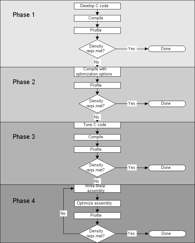
CCS includes an optimization tutorial that provides a recommended code development flow consisting of four phases (Figure 1). (A similar tutorial is in the TMS320C6000 Programmer’s Guide.)
 

Code Development Flow


Figure 1. Code Composer Studio’s optimization tutorial recommends a code development flow consisting of four phases. The first three phases focus on utilizing the optimization abilities of the ‘C6000 compiler to achieve high code performance while maintaining the code in C. The last phase involves linear assembly coding of the portions of the code whose performance needs to be improved further. (This figure is based on the one on p. 1-4 of theTMS320C6000 Programmer’s Guide).


Phase 1 involves compiling and profiling your baseline C code. Before you begin any optimization effort, use the profiling tools to identify the performance-critical areas in your code.


Phase 2 involves compiling with the appropriate optimization options and analyzing the feedback provided by the compiler to improve the performance of your code.


Phase 3 is a critical phase during which you use a number of techniques to tune your C code for better performance. One technique is to provide as much information as possible to the compiler so that it can perform adequate software pipelining, especially for MIPS-intensive loops. Another is to analyze the dependencies between instructions. If the compiler determines that two instructions are independent, it attempts to schedule them to execute in parallel. You can help the compiler make those determinations.


A third technique is to refine your C code to use the C6000 intrinsics, which are special functions that map directly to in-lined C6000 instructions. These functions are usually not easily expressed in C. Intrinsics allow you to have more precise control over the selection of instructions by the compiler.


Phase 4 is needed if the performance of certain areas of your code must be improved beyond the tuning phase. After yet another profile of the code, you can extract the performance-critical areas and rewrite them in linear assembly language. This form of assembly code doesn’t require that you provide functional unit selection, pipelining, parallelization, or register allocation; those tasks will still be performed by the compiler. It will, however, give you more control over the exact C6000 instructions to be used. You can also pass more useful information to the tools, such as which memory bank is to be used.

Phase 1: Develop C Code


Phase 1 establishes your baseline. You have a goal-for example, your system requirement might be a statistical mix of 48 modems on one 200-MHz C6201. Always maintain the C-coded baseline as your reference code. Because it’s often developed very straightforwardly, leaving it as a reference will be valuable if you have to diagnose a problem. Make your improvements there, then factor them into the optimized version to produce a bit-exact version.


Phase 2: Compile With Optimization Options


The optimizer, combined with a judicious memory layout, can more than double the number of modems on one chip. Allocate a few weeks for the effort. But note that the optimizer is capable of “breaking” the modems in a few places, so you may have to modify some pieces of the C code. Also, you may find that some of the changes you make to the C code to improve the optimizer’s results when using CCS 1.1 aren’t required when using the release 1.2 optimizer; therefore move to 1.2 if you can.


Phase 3: Tune The C Code


XDSP CompliantThere are a number of techniques to refine your C code and greatly increase its efficiency. The goal is to allow the compiler to schedule as many instructions as possible in parallel by providing information concerning the dependencies between instructions. Dependency means that one instruction must occur before another. The programmer can use certain keywords that give the compiler hints as it tries to determine dependencies.


Another useful technique in the tuning phase is to use intrinsics, which are special functions that map directly to C6000 assembly instructions. Some intrinsics operate on data stored in the low and high portions of a 32-bit register. This means that if you are operating on a stream of 16-bit values, you can use word (32-bit) accesses to read and process two 16-bit values at a time. This type of optimization is called SIMD (Single Instruction Multiple Data).


Even though phases 2 and 3 may double the number of simultaneous instances of the code running on one chip, the modems are still coded in C that’s easy to understand and maintain.

Phase 4: Circular Addressing


At this point, if your performance requirements are not yet met, the next step is to convert MIPS-intensive portions of the code to linear assembly. If you’re optimizing modems, you can employ circular addressing. Modems use a number of delay lines for the different filters, resulting in MIPS-intensive memory shifting. You can avoid that by employing the circular addressing feature of the C6000 in your linear assembly code. It’s not unreasonable to set a goal of doubling the number of modems from 12 to 24 in this step alone.


For the most part, a modem is a series of filters. Each filter is computed from a sequence of input data, or taps, and an equal number of coefficients. A multiply-accumulate operation is performed between each tap and a corresponding coefficient. After the computation, the taps are shifted to make room for the new input (Fig. 2a). Circular addressing changes the starting point for the MAC cycle, eliminating the shifting altogether (Fig. 2b).


Circular Addressing


Figures 2. new sample, x5, is added to the delay line of a four-tap filter (x1 is the oldest sample in time) using the sample-shifting method. Three shifts are needed before x5 is placed at the top of the delay line (a). Using circular addressing, register A4 (set up to be used in circular mode) automatically wraps back to the beginning of the delay line after x4 is added and the end of the delay line is reached. When x5 is added, it overwrites the oldest available sample, x1, thereby eliminating the shifting altogether (b).


Without hardware support for this operation, the C code for the iterative loop is of the form in Listing 1 (See Appendix). The C6000 has hardware support for circular addressing, though. By setting the addressing mode register (AMR) appropriately, you can specify the general-purpose register(s) that will be used for circular addressing, as well as the size of the memory block that will be addressed circularly. Listing 2 (See Appendix) shows the circular addressing implementation of the C routine for the iterative loop.


Just as using the optimizer has its challenges, so can adding circular addressing. You might find that you can add circular addressing and then the optimizer breaks it. It turns out the optimizers in both CCS 1.1 and 1.2 don’t take circular addressing into account. For example, the optimizer will often move an address from a register configured for circular addressing to another register before performing address manipulations.


When using the optimizer with circular addressing, you might have to experiment with a number of alternative codings to arrive at a solution that the optimizer respects. (According to TI, release 2.0 of CCS, scheduled for release in the first quarter of this year, will support circular addressing directly from C.)


You should see a significant improvement with circular addressing. Take the V.29 fax receiver as an example: After the first three phases of our project, it consumed 222,188 cycles for each 10 ms of PCM data (80 samples). By modifying just the first two sections-the pulse-shaping and Hilbert filters-to circular addressing, we brought that down to 185,759 cycles. Changing the interpolating and baud-timing recovery filters to circular addressing mode reduced it to 155,677. Finally, changing the adaptive filtering and update routines shrank the cycle count down to 101,429-a reduction of better than 55%. (For a more in-depth discussion of circular addressing on the C6000, refer to the TI Application Report Circular Buffering on TMS320C6000[SPRA645.PDF].)


Since a V.17 fax receiver is essentially the same code as the V.29 fax receiver but executing from different tables, these changes cause similar reductions to the V.17 fax receiver. However, we still need to optimize the Viterbi decoder.


If your modems require Viterbi decoding, you’re in luck, since TI has drum-tight assembly code. Of the three common modems used to transfer fax-image data, only the V.17 fax modem (14,400 bits/s) uses Viterbi decoding.


Trellis Coding is a forward error-correction scheme that reduces a modem’s bit-error rate for a given amount of channel noise by adding certain redundant information to the channel. The information reduces the chance that noise will create data errors, thus in effect increases the distance between code points. The Viterbi decoder decodes the Trellis sequence and determines the most likely set of transmitted points. However, it’s expensive in terms of MIPS. Commetrex’s C-coded Viterbi decoder alone took 140% of the cycles that the entire V.29 fax receiver took. In other words, the V.17 fax receiver was 2.4 times as expensive as the V.29 (9,600 bits/s).


Help is available on the TI Web site (www.ti.com). When you download Implementing V.32bis Viterbi Decoding on the TMS320C6200 DSP (SPRA444.PDF), you’ll find the decoder in very tight assembly code. You can’t just drop it in, though. You’ll have to adapt it to your environment.


To make the decoder reentrant, change global variables to per-channel contexts and watch for bugs. You should achieve spectacular results: A straight C-coded Viterbi consumes approximately 150,000 cycles for 80 samples. Substituting the TI-provided assembly code takes that down to an incredible 8,000 cycles. The Commetrex V.29 fax receiver is now 101,429, and the V.17 fax receiver only 108,840 cycles-and we haven’t begun to “vectorize.”


Using a statistical mix of modems yields 28 simultaneous channels. In worst-case nonblocking terms, that’s 18 simultaneous V.17 fax receivers. You should receive similar results for similar algorithms by using the optimizer and circular addressing.

Beyond Phase 4: “Vectorize”


If at this stage you haven’t yet reached your performance requirements, the next step in your optimization effort might be to consider changing the flow of data through your code in order to reduce function calls and utilize more loops which can be optimized easily. For modems, one approach to accomplish that is to “vectorize” the algorithm’s implementation. The term comes from referring to an array of samples of data as a vector as opposed to a scalar datum.


The sample rate section of the receiver consists of the following components in series: The pulse-shaping filter, the Hilbert transformer, the demodulator, and the interpolator. Without vectorization, the sample rate section of the receiver processes one sample at a time, taking it through each successive section. Thus the overhead of calling each filter in the sample rate section is incurred 80 times for each 80-sample buffer. With vectorization, the sample rate section is called once for each 80-sample buffer. An input buffer of 80 samples is then passed to the pulse-shaping filter, which produces 80 samples to be passed to the Hilbert filter, which in turn produces 80 outputs, and so on. In the sample rate section, the number of function calls required to process 80 samples is reduced from 320 to just 4. In addition, processing the input buffer in a loop format as opposed to sample-by- sample allows the optimizer to do a better job of pipelining, significantly improving efficiency.


We haven’t completed the vectorization phase of this project, but we will report the results on our Web site (www.commetrex.com) when we do.

Appendix


Listing 1. Circular Addressing Loop Without Hardware Support


 * Routine Name: FIR_Filter_Shift
 *
 * Description:
 *    Performs fixed-point FIR filter with data move.
 *
 * Calling Sequence:
 *
 * INT16 FIR_Filter_Shift(INT16   *taps,
 *                                      INT16   *coefs,
 *                                      UINT16  length,
 *                                      UINT16  base)
 *    Where:
 *       taps    = pointer to filter taps delay line
 *       coefs  = pointer to filter coefficients
 *       length = length of taps delay line
 *       base   = base of filter coefficients
 *
 * Returns:
 *    An INT16 filtered sample
 *
 ******************************************************************/

INT16 FIR_Filter_Shift(INT16   *taps,
                                     INT16   *coefs,
                                     UINT16  length,
                                     UINT16  base)
{
   UINT16 i;
   INT32  sum=0;

   for( i = 0; i < length; i++ )
   {
      sum += ( taps[length-i-1] * coefs[i] );
      taps[length-i-1] = taps[length-i-2];
   }

   return( ( sum+(1<<(base-1)) ) >> base );  /* Round and remove base */
}


Listing 2. FIR Filter Using Circular Addressing With Hardware Support


; Replacement for FIR_Filter_Shift
;
; PARAMETERS:
;             A4 - (in)  *coefs
;             B4 - (in)  *taps /* base address of circular buffer */
;             A6 - (in)  length /* length of delay line */
;             B6 - (in)  block_size
;             A8 - (in)  write_offset; where the next value will be written
;             B8 - (in)  base
;

   .global _FIR_Filter

_FIR_Filter  .cproc  coef_block,taps,A6,B6,A8,base

   .reg old_amr, ar, coef, sum1, dl, one, round, offs

   ; coef_block = coefs + ((length-1) * sizeof(short))
   SUB A6,1,dl                             ; dl = length - 1
   SHL dl,1,dl                               ; dl = (length-1) * sizeof(short)
   ADD coef_block,dl,coef_block ; coef_block = coefs + dl

   SHL B6,16,B6
   SET B6,8,8,B6
   MVC AMR,old_amr                  ; old_amr = AMR
   MVC B6,AMR                           ; AMR = addressing_mode

   ; acc == A1
   ZERO A1                                  ; A1 = 0

;   ar + write_offset is where we will write next.
;   advance to the most recent word (write_offset - 2)
;   ar = taps + (write_offset - 2);
   SUB A8,2,offs
   ADDAB taps,offs,taps
   MV A6,dl

startloop_16: .trip 1
   LDH *taps--,ar
   LDH *coef_block--,coef
   MPY ar,coef,sum1
   ADD sum1,A1,A1
   SUB dl,1,dl
[dl] B startloop_16

   SUB base,1,round   ; start rounding
   MVK 1,one
   SHL one,round,round
   ADD round,A1,A1
   SHR A1,base,A1     ; A1 contains rounded answer

   MVC old_amr,AMR
   .return A1
   .endproc